Element Transformation Example 01: Zero Length Spring.
The example highlights the command ELMTRANS.
The option has two main functions:
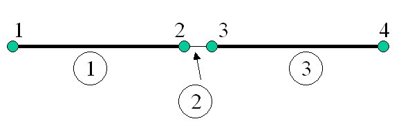
In the example, the two beams, 1 and 3 have no common nodes.. Instead, a two node non linear spring (element no 2) connects node 2 and 3, which have identical coordinates. The length of the spring therefore becomes equal to Zero, and the local coordinate system cannot be defined the usual way (with the X-axis going from end1 to end 2 etc).
The command:
ElmTrans Loc 2 Elem 2
means that element 2 (the non linear spring) gets identical transformation matrix as the beam element attached to local end 2 of the spring. This means that node 3 (which is end 2 of the spring) defines the orientation of the spring as the system rotates. The initial coordinate system of the zero length spring is identical to the system for beam element 2. .
If many springs should be modelled it is recommended to use same systematic numbering for all springs, and the definition could be done by only one input line. In such cases, the "ListType" should typically be Material, (instead of listing all spring element ID's).
The simple demo example is described in the following two files:
=> Usfos Control File
=> Model File
Figure 1 Element model.. Nodes and element numbers.
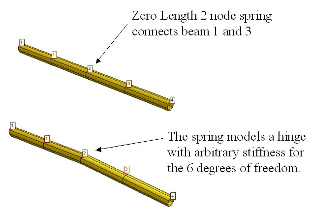
Figure 2 Element 1 and 3 have a hinged connection.
.